Upon completion of the injection mold, navigating the acceptance process can be daunting. BFY Mold’s editor outlines key criteria for evaluating the molded products, mold appearance, material, functionality, and more to guide you through this crucial phase.
Injection Mold Acceptance Criteria
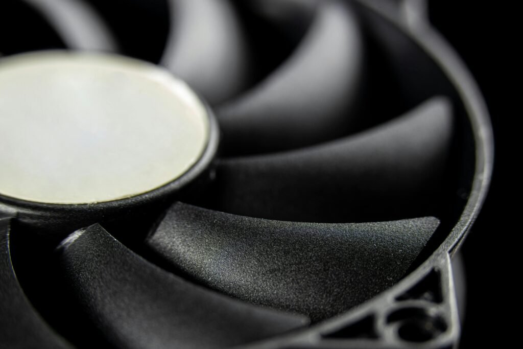
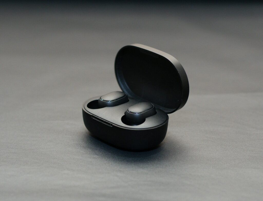
a: Appearance, Size, and Fit of Molded Products
- Defects are not allowed on product surfaces.
- Weld marks within specified limits.
- No shrinkage in visible areas.
- Ensure plane evenness and meet assembly requirements.
- There are no air marks or bubbles in obvious parts.
- Geometric shape and dimensions per mold drawings.
- Product wall thickness requirements.
- Ensure product coordination and matching intervals.

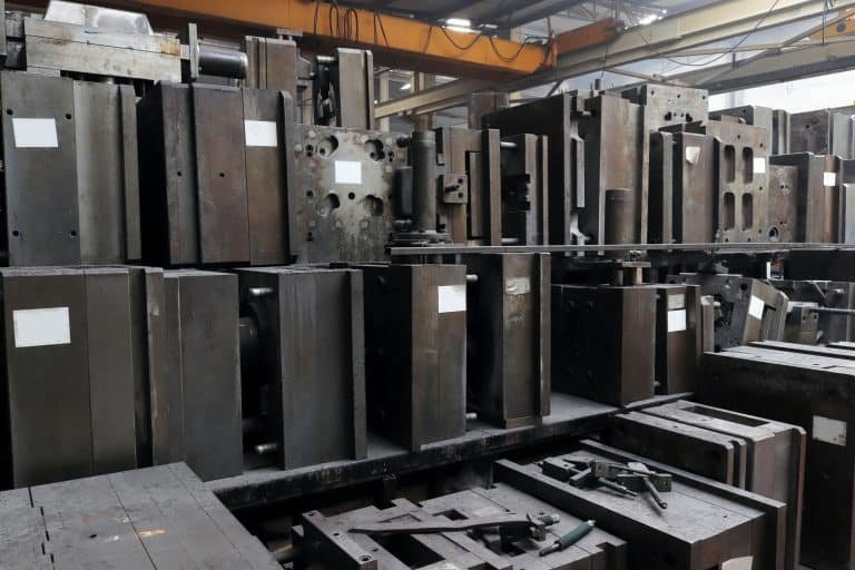
b: Mold Appearance
- Complete and clear mold nameplate.
- Firmly fixed nameplate with clear characters.
- Cooling water nozzle requirements.
- Mold accessories should not interfere during installation.
- Mold ejection hole size as per machine requirements.
- Marking installation direction and “UP.”
- No defects affecting the appearance of the mold base surface.
- Easy hoisting, no disassembling during hoisting.
c: Mold Material and Hardness
- Standard mold base.
- Mold parts made of higher-than-40Cr materials.
- Corrosion-resistant materials for corrosive plastics.
- The molded part’s hardness is not less than 50HRC.

d: Eject, Reset, Pull Out the Insert Core, and Take Out the Parts
- Smooth ejection without stagnation or abnormal sound.
- Polished sloping top surface.
- Oil grooves for sliding parts with nitrided surface.
- Numbered and positioned ejector pins.
- Limited ejection distance.
- Standard return spring.
- Slider and core-pulling with travel limits.
- Wear-resistant plate for large sliders.
- Barbs on ejector pin for easy removal.
- Smooth ejection with grooves or etched patterns.
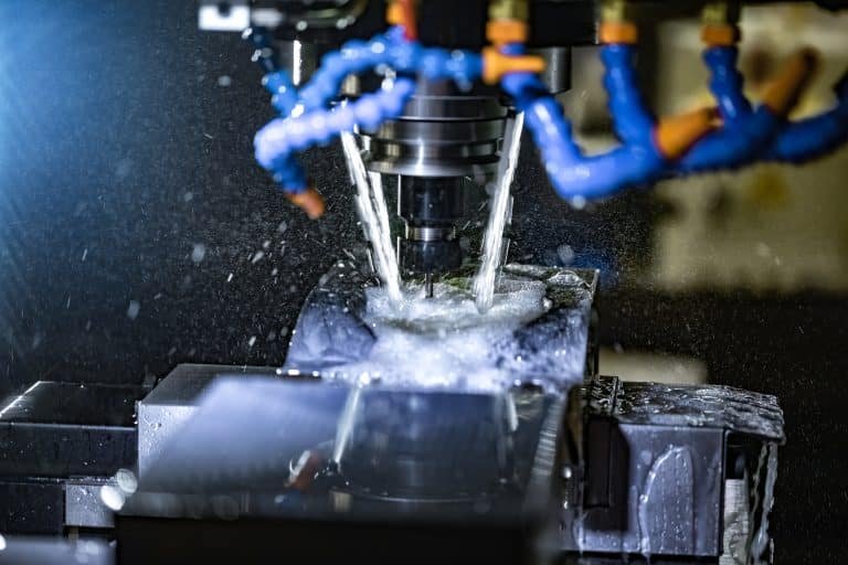
e: Cooling and Heating System
- Fully unblocked cooling/heating system.
- Reliable sealing, no leaks under 0.5MPa pressure.
- Sealing ring smeared with butter.
- Smooth water and oil flow channels.
- Centralized water supply for front and rear molds.
- Cooling water channel diameter between 8~12mm.
f: Gating System
- Gate setting does not affect product appearance.
- Reasonable flow channel design.
- Trapezoidal or semicircular sub-runner for three-plate mold.
- Material break handle and ball head pull rod requirements.
- Machine processing for gate and runner.
- Smooth extension for the cold material hole.
g: Molding Part, Parting Surface, Exhaust Groove
- Clean front and rear mold surfaces.
- The gap around the rounded corners of the insert.
- Clean and tidy parting surface.
- The exhaust groove depth is less than the plastic overflow value.
- Reliable positioning and fixing of inserts.
- No copper or iron sheets under inlays.
- Uniform skin texture and sandblasting.
- Screw columns with barbs for shrinkage measures.
- Uniform product wall thickness.
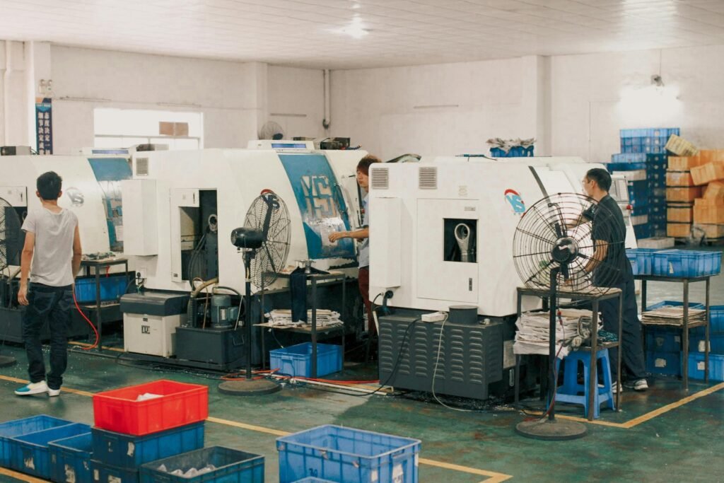
h: Injection Molding Production Process
- Stable and repeatable injection molding production.
- Injection pressure within 85% of the machine’s rated maximum.
- Injection speed requirements during production.
- Holding pressure not exceeding 85% of the actual maximum.
- Clamping force below 90% of rated force.
- Easy and safe product removal and nozzle material.
- Easy installation and reliable fixing of inserts.

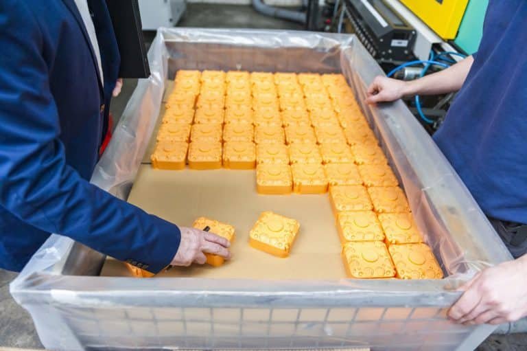
i: Packaging and Transportation
- Cleaned mold cavity with anti-rust oil.
- Lubricated sliding parts.
- Blocked sprue sleeve feed port.
- Equipped with clamping piece.
- Complete spare parts with detailed lists.
- Sealed water, liquid, gas, and electricity inlets/outlets.
- Outer surface spray-painted as required.
- Moisture-proof, waterproof, and bump-proof packaging.
- Complete documentation and electronic files.
Conclusion
Ensure that your injection molding production process maintains stability and repeatability, with parameters adjusted within normal conditions. Finally, meticulous packaging and transportation protocols, along with comprehensive documentation, guarantee the integrity of the mold, its components, and the seamless transition to production.