
CNC Machining Services for Custom Parts
Manufacture custom components from your drawings. Review geometry, material, critical dimensions and surface requirements with BFY Mold for prototype and production machining.
CAD model · Material · Quantity · Critical requirements
On this pageJump to the information you need
Translate your drawing into a machining plan
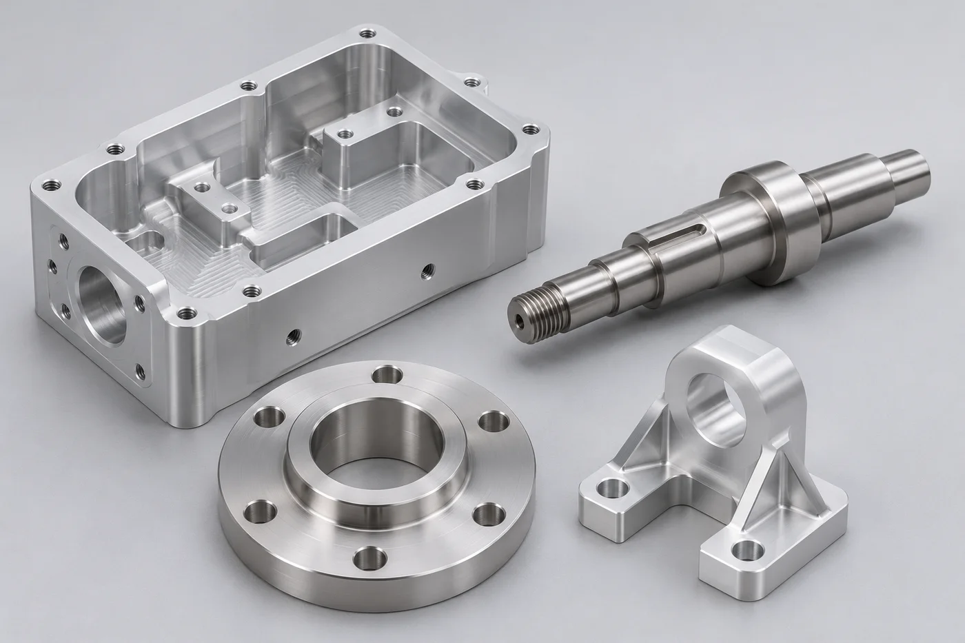
CNC machining removes material from stock to produce the required geometry. It can be suitable for functional prototypes, fixtures and production components where the material and design can be machined effectively. Tool access, setup, workholding and inspection influence what is practical.
- Review milling or turning requirements against the part geometry
- Identify critical tolerances and mating or datum features
- Plan material, surface finish and inspection together
CNC Machining: Specifications & Project Requirements
| Starting files | 3D model plus a 2D drawing for tolerances, threads and other requirements |
|---|---|
| Materials | Discuss aluminum, steel, stainless steel, brass and machinable plastics for your application |
| Geometry review | Tool access, deep pockets, internal corners, thin walls and workholding |
| Tolerances | Confirm achievable tolerances for the material, size, features and inspection method |
| Surface finish | Specify the finish and any surfaces that must remain untreated |
| Production planning | Prototype or repeat quantities, subject to drawing and process review |
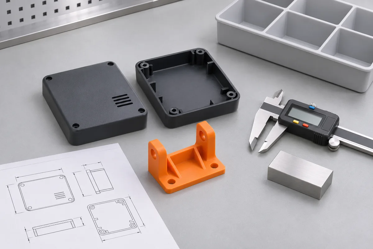
Final feasibility, tolerances, quantities and timing are confirmed after review of your drawings and requirements.
Specify the features that matter
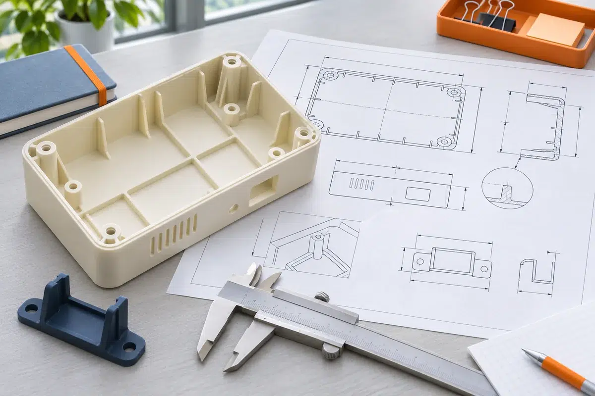
Not every surface needs the tightest tolerance. A drawing that distinguishes critical interfaces from general features helps focus manufacturing and inspection where they are needed.
Drawing & datums
Mark critical dimensions, fit requirements, threads and datum references. Provide the drawing revision that controls the order.
Material & stock
Specify the alloy or plastic grade and any material documentation requirements. Material and geometry affect the machining approach.
Finish & inspection
Identify cosmetic surfaces, coatings and critical measurements. Confirm whether finishing affects mating dimensions.
From one drawing to a connected production plan
Review the requirements at each stage, from engineering and tooling to samples, production checks and delivery.
Review the part before choosing the process
- Project inputs3D CAD, drawing revision, mating components and visible surfaces.
- Review prioritiesPart geometry, assembly, material and expected production quantities.
- Agreed next stepClarify open requirements and confirm the quotation scope.
Connect geometry, workholding and inspection
- Technical scopeReview tool access, setups, material and critical features.
- Approval criteriaAgree drawing requirements, sample checks and the review process.
- Project planConfirm the work scope and milestones before manufacturing.

Manufacture against the agreed specification
- Approved referenceConfirm the drawing revision, material and agreed sample or specification.
- Process requirementsIdentify critical features, appearance and the checks required for the project.
- Change controlDiscuss changes to the drawing, material or requirements before proceeding.
Keep acceptance and delivery requirements clear
- InspectionDefine the critical dimensions, appearance checks and required records.
- PackagingAgree protection, quantities and handling requirements for shipment.
- Repeat productionKeep drawing revisions and approved requirements clear for later orders.
CNC Machining FAQs
A clear specification helps us review the manufacturing route and prepare a useful quote.
Do I need both a 3D model and a 2D drawing?
A 3D model describes the geometry, while a 2D drawing helps define tolerances, threads, finishes and inspection requirements. Sending both makes the review more complete.
What tolerances can you achieve?
Tolerance capability depends on material, size, geometry, setup and measurement. Mark critical dimensions so achievable requirements can be confirmed for the specific part.
Can plastic parts be CNC machined?
Many engineering plastics can be machined, depending on geometry and requirements. Share the grade and application so material behavior and workholding can be considered.
How is machining lead time determined?
Timing depends on material availability, geometry, quantity, setups, finishing and inspection. A project schedule is confirmed after drawing review.
Related manufacturing services
Request a CNC Machining Quote
Tell us the material, quantity, critical dimensions, finish and target schedule. Add your drawing or model so we can review the manufacturing requirements.
Attach PDF, JPG, PNG or ZIP files, up to 50 MB per file. Put STEP/STP, IGES or X_T CAD files in a ZIP archive. You can also email info@bfymold.com.