Common Defects in Injection Molding and How to Avoid Them
Avoiding common injection molding defects is crucial for maintaining product quality and efficiency in manufacturing. By understanding the typical issues that can arise, such as warping, sink marks, and air bubbles, manufacturers can implement effective strategies to mitigate these problems. This proactive approach not only enhances the durability and appearance of the final product but also reduces waste and production costs. In this article, we will explore six essential tips to help you identify and prevent these defects, ensuring a smoother injection molding process and superior results.
Injection molding is a highly efficient and versatile manufacturing process, but it has challenges. Defects can arise, leading to wasted materials, increased costs, and production delays. Manufacturers can ensure high-quality, reliable parts by understanding common defects and how to prevent them.

1. Warping
Warping occurs when different parts of the molded item cool and shrink at different rates, causing the part to twist or bend out of shape. This defect can compromise the structural integrity and appearance of the final product.
Prevention Tips:
- Material Selection: Choose materials with uniform shrinkage rates. Semi-crystalline polymers tend to warp more than amorphous polymers.
- Mold Design: Ensure uniform wall thickness throughout the part to promote even cooling. Incorporate ribbing to add strength without increasing wall thickness.
- Cooling Rate: Control the cooling rate by optimizing mold temperature and coolant flow. Slow, uniform cooling reduces the risk of warping.
- Gate Placement: Position gates strategically to ensure an even flow of material and consistent cooling.

2. Sink Marks
Sink marks are depressions or dimples that form on the surface of the molded part, typically over thicker sections where the material has cooled and shrunk unevenly.
Prevention Tips:
- Material Choice: Use materials with lower shrinkage rates or those that are less prone to sink marks.
- Part Design: Design parts with uniform wall thickness. Avoid thick sections, or use coring to hollow out thick areas.
- Process Parameters: Increase packing pressure and duration to ensure sufficient material is fed into the mold cavity during cooling. Optimize cooling time to allow the part to solidify properly.
- Mold Temperature: Maintain an appropriate mold temperature to facilitate even cooling.

3. Bubbles (Air Traps)
Bubbles, or air traps, occur when air gets trapped in the mold cavity, leading to voids or bubbles within the part. These can weaken the part and affect its appearance.
Prevention Tips:
- Mold Venting: Ensure proper venting in the mold to allow trapped air to escape. Venting can be achieved through the use of vents, runners, and gates.
- Injection Speed: Adjust the injection speed to allow air to escape before the material fills the cavity. Slower injection speeds often help in reducing air traps.
- Material Drying: Thoroughly dry hygroscopic materials before molding to prevent moisture from causing bubbles.
- Gate Design: Optimize gate design and placement to ensure smooth flow and minimize turbulence that can trap air.
4. Flash
Flash is the excess plastic that seeps out of the mold cavity and solidifies, creating unwanted thin layers or protrusions along the parting lines.
Prevention Tips:
- Clamp Force: Ensure sufficient clamping force to keep the mold halves tightly closed during injection.
- Mold Maintenance: Regularly inspect and maintain mold surfaces to ensure they are clean and free of damage or wear.
- Process Parameters: Optimize injection pressure and speed to prevent material from forcing its way out of the mold cavity.
- Mold Design: Incorporate precise parting line tolerances and properly align mold components.

5. Short Shots
Short shots occur when the mold cavity is not filled with material, resulting in incomplete parts.
Prevention Tips:
- Material Flow: Ensure adequate material flow by maintaining appropriate melt temperature and reducing viscosity.
- Injection Pressure: Increase injection pressure and speed to ensure the material reaches all parts of the mold cavity.
- Gate Size and Location: Optimize gate size and placement to facilitate complete filling of the mold.
- Venting: Improve mold venting to prevent air from blocking material flow.
6. Burn Marks
Burn marks are discolorations or charred areas on the part caused by trapped air heating up to the point of burning.
Prevention Tips:
- Venting: Enhance mold venting to allow trapped air to escape, reducing the risk of burning.
- Injection Speed: Reduce injection speed to minimize the compression of trapped air, which can cause burning.
- Material Drying: Properly dry the material to prevent moisture from contributing to burn marks.
- Gate Design: Optimize gate design to ensure smooth and consistent material flow.
By implementing these preventative measures, manufacturers can significantly reduce the occurrence of common injection molding defects, leading to higher-quality products and more efficient production processes.

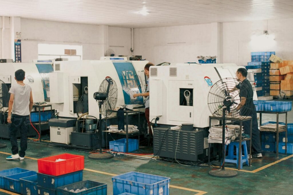
About BFY Mold
At BFY Mold, we specialize in providing top-notch injection molding and mold manufacturing services. With our state-of-the-art factory, we offer mass production, on-demand production, CNC machining, and mirror spark services. Our team is dedicated to delivering high-quality, precision-engineered parts that meet the specific needs of our clients. Contact us today to learn how we can help you achieve your manufacturing goals.
10 Other Possible Scenarios For Injection Molding
1. How to Prevent Warping in Thin-Walled Plastic Parts?
Maintain uniform wall thickness (1.5–3.0 mm) and use mold temperatures ≥80°C for materials like ABS. Top suppliers utilize conformal cooling channels (±1°C variance) to minimize thermal stress.
2. What Causes Sink Marks and How to Avoid Them?
- Root Cause: Thick sections are cooling more slowly than thin areas
- Fix: Limit rib-to-wall ratio to ≤60% and increase holding pressure (80–95% of injection pressure)
3. How to Eliminate Air Traps and Burn Marks?
- Venting: 0.03–0.05 mm vents at weld lines
- Process: Reduce injection speed by 15–20% for complex geometries
4. Why Do Short Shots Occur and How to Resolve Them?
| Cause | Solution |
| Low melt temp | Increase by 10–20°C (per ASTM D3641) |
| Insufficient pressure | Raise injection pressure 5–10% |
5. How to Prevent Flash in High-Pressure Molds?
- Tooling: Ensure mold clamping force ≥3 tons/cm²
- Material: Use low-viscosity resins (MFI ≥15 g/10min)
6. What Mold Design Features Reduce Ejection Failures?
- Draft angles ≥1.5° for textured surfaces
- Ejector pins placed within 5 mm of undercuts
7. How to Avoid Delamination in Multi-Material Parts?
- Material Pairing: Match shrinkage rates (Δ ≤0.2%)
- Process: Maintain 5–8°C higher melt temp for substrate
8. Why Do Weld Lines Form and How to Strengthen Them?
- Redesign: Relocate gates using Moldflow simulations
- Parameters: Raise melt temp by 15–20°C at weld areas
9. How to Control Splay (Silver Streaks) in Transparent Parts?
- Dry hygroscopic resins (e.g., PA66) to ≤0.02% moisture
- Reduce screw RPM by 20–30% to prevent overheating
10. What Certifications Ensure Defect-Free Production?
- ISO 9001: Quality management systems
- SPI Class 101: Precision tooling standards