An insert molding design review should connect the metal insert, the surrounding plastic and the finished assembly. A thread specification alone does not tell a mold maker how to locate the insert, keep plastic out of functional areas or evaluate retention after molding. This checklist helps engineering and purchasing teams prepare those decisions before requesting tooling.
Use it alongside the insert molding service review. For a comparison of manufacturing routes, see overmolding versus insert molding.
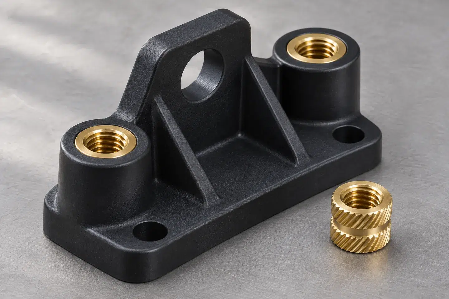
1. Define the Insert and Assembly Baseline
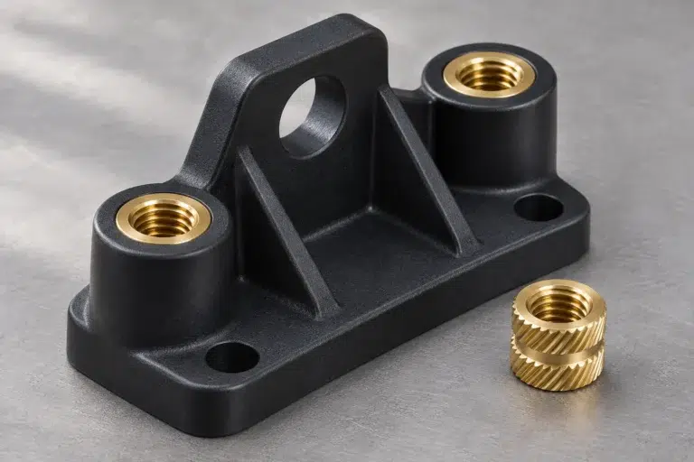
In insert molding, a preformed component is positioned in the tool before plastic is molded around it. This differs from installing an insert into an already molded part. The installation route matters because it changes the insert features, locating arrangement and manufacturing review. Protolabs’ insert molding guidelines describe this basic process distinction.
Prepare separate, matching revisions for the insert drawing and the finished plastic assembly. Identify the insert supplier, material, finish and relevant tolerances. If an alternative insert is proposed, treat it as a design decision: the same nominal thread does not establish equivalent outside geometry or retention features.
| Review Item | Information to Provide | Decision to Record |
|---|---|---|
| Insert identity | Part number, drawing revision, material, finish and supplier | Approved insert specification and substitution process |
| Location | Datum features, orientation and position requirements | How the insert is located and checked |
| Exposed features | Threads, terminals, sealing or mating surfaces | Where plastic and flash are unacceptable |
| Plastic body | Resin grade, wall geometry, ribs and mating parts | Open DFM issues and approved changes |
| Service loads | Fastening, axial, rotational and environmental requirements | Applicable tests and acceptance limits |
| Sample release | Critical dimensions, appearance and inspection requirements | Evidence required before production approval |
2. Review Positioning and Exposed Surfaces
Mark which feature determines insert position in the assembly. A threaded insert may be held by one feature during molding while its final position is measured from another. Identify both references so the tool review does not depend on an unstated assumption.
Provide a section view showing the insert boundary. Highlight thread entrances, electrical contact areas and any surfaces that must remain free of plastic. Ask the mold designer to review the proposed locating and shut-off arrangement, loading orientation and access for removal of the finished part. Do not prescribe a universal clearance without considering the actual insert tolerances and tool design.
3. Separate Torque, Pull-Out and Assembly Requirements
Torque resistance and axial pull-out resistance describe different failure modes. SPIROL’s plastic joint design guidance explains why insert selection should begin with assembly performance requirements, with plastic specification, component design and installation also affecting performance.
For your project brief, distinguish the torque used to assemble a fastener from a test intended to evaluate insert rotation. State how a pull-out test would load and support the component. Include the mating screw, mating part and relevant test conditions. A satisfactory result under one fixture or condition should not be treated as proof for every load direction or operating environment.
Review the resin and surrounding plastic geometry together with the insert. Consider wall transitions, nearby ribs, available space and how the part will be supported in service. Required dimensions and acceptance limits should come from the drawing and application review, not a generic insert-size rule.
4. Agree What Trial Samples Must Demonstrate
Organize the sample review around three questions:
- Is the insert in the right place?Check identity, orientation, location and exposed features against the drawing.
- Does the assembly meet its requirements?Review dimensions, fastening or retention checks and mating-part fit using the agreed methods.
- What is approved for production?Record the drawing revision, material, sample identity, open issues and release decision.
Record any insert movement, unwanted plastic on threads, visible cracking or incomplete filling as a specific issue. Link the observation to a sample and location, then agree the next investigation or correction. Describe a proposed change separately from a failure against the existing requirement.
5. Send a Complete Insert Molding RFQ Pack
Include the insert model, finished-part CAD, dimensioned drawings, resin specification, expected quantities, visible surfaces, critical dimensions and target dates. State who supplies the inserts and which records or tests the order requires. An annotated assembly section can make the request clearer than several disconnected files.
If the design still has open questions, request an injection mold design and DFM review before treating the quotation as a final manufacturing commitment. Review the material candidates against the actual application and selected grade.
Insert Molding Design FAQs
Can I use an insert designed for installation after molding?
Do not assume it is interchangeable with a molded-in insert. Confirm the insert manufacturer’s intended installation method and review its geometry with the mold designer.
Is there a standard pull-out value for all insert molded parts?
No single value establishes suitability for every assembly. Specify the required performance, material, geometry and test conditions for the finished component.
Should I select the plastic before requesting a quote?
Provide the exact grade if it is fixed. Otherwise describe the application and performance requirements, and identify material selection as an open review item.
What is the next step if my design is not final?
Share the current CAD, insert details and unresolved questions. Separate feasibility review from production approval and agree what must be resolved before tooling.
Review Your Insert Molding Project
Send the insert and part drawings, material requirements and expected quantities to discuss the tooling review and quotation scope.
Request a Project Review →