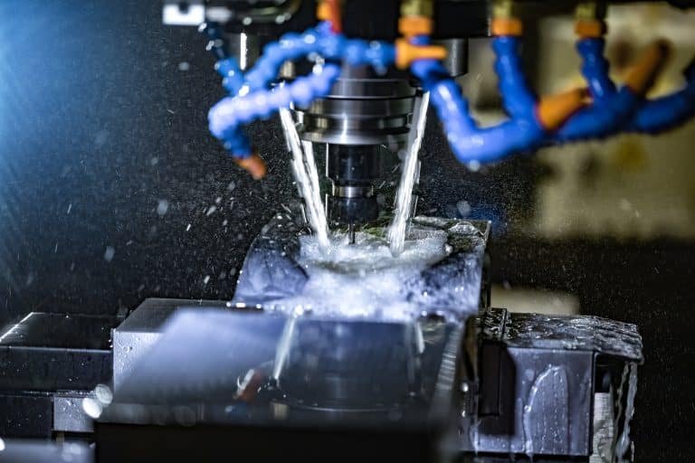
1. Machining: Understanding The Different Fit Types
“Press-fit” and “slip-fit” are several kinds of fits commonly applied in the fixation of parts, specifically in the assembly of mechanical elements in precision machining. The fit of two parts is the dimensional relationship between them, how tight or loose they are when assembled.
Depending on how strong of a restriction is required as well as the tolerances involved and the materials of the shaft and hole, press fits and slip fits have different applications. In this article, we will take a more in-depth look at what these fit are, how they are achieved, and the major differences between them to ensure you have a clearer understanding of fits and how they are used in the manufacturing and assembly processes.

2. What is a Press Fit?
A press fit is a kind of interference fit in which one of the parts (usually a shaft or pin) has a slight dimension larger than the hole or opening it will be inserted into. It’s tight enough that the parts must be forced together to create a pressurized, or “interfered,” fit between them.
This results in the deformation of the materials involved, thus resulting in a strong mechanical bond. A press fit is a type of fit. Such a fit is used in applications where the joint has to be permanent or has good interference resistance. It includes bearing installation and anything to do with fitting a gear onto a shaft.

3. How Do You Calculate Press Fit Force?
Calculate the Press Fit Force Press fit force is defined as the force needed to press a component into a hole and obtain a tight fit. The force is typically computed from the interference (difference in the dimensions of the parts) and material properties (elasticity, hardness, etc).
Press fit force can be calculated using the following formula:

Where:
- F is the press fit force.
- d is the diameter of the smaller part (the shaft).
- D is the diameter of the larger part (the hole).
- h is the height or length of the fitting surface.
- E is the modulus of elasticity of the material.
- L is the length of the interference zone.
In simpler terms, the press fit force calculation depends on the difference in size between the two parts (the interference), the geometry of the parts, and the material properties.
4. How is a Press Fit Achieved?
The steps taken to create a press fit include:
- Select Required Interference: This is the difference in the part dimensions. The interference should be chosen depending on the required strength and application.
- Force: The big part is pressed into the smaller part using a press or similar device. The force slightly bends the materials, enabling a snug fit.
- Keep within tolerances: The manufacturer has taken care to keep tolerances applicable to this fit and resistance, heading towards proper interference so that the hold of the fit stays.
A successful press fit requires just the right amount of interference between tensile forces to ensure that a deformed zone is created, leading to a secure, permanent joint.
5. What is a Slip Fit?
Unlike a press fit, a slip fit is a type of fit where the sizes of the two pieces are close enough to prevent interference. That is, the hole is a touch larger than the shaft, so the shaft can slip or slide freely in the hole.
A slip fit prevents the use of significant force to fit parts to each other, so slip fits are often used where parts are assembled and/or disassembled frequently. These fits are appropriate for applications such as bearings, in which components must slide or rotate with little friction or tight engagement.

6. How is Slip Fit Achieved?
The shaft and hole are machined so close that they will slip together with little more than the slightest wiggle. Slip fit can be obtained in the following ways:
- Select Appropriate Tolerances: Machined widths of both parts lead to a tiny, controlled space between the shaft and the hole. The clearance must be sufficient to enable smooth displacement during operation without slippage.
- Simple Assembly: Compared to the press fit, no big force is necessary to compose the parts. They can be inserted by hand or with a bit of mechanical help.
- Check for Freeness: The gap needs to be wide enough so that flexible fittings don’t bind or wear too much but also wide enough to be functional.
Slip fits usually require less force than press fits, and no special tooling is needed to fit the components together.
7. Press Fit vs. Slip Fit: A Detailed Comparison
| Feature | Press Fit | Slip Fit |
| Definition | An interference fit with tight tolerances. | A clearance fit where parts can move freely. |
| Assembly Process | Requires force for assembly, typically via a press. | Parts slide or slip into place without force. |
| Mechanical Bond | Provides a strong, permanent connection. | No permanent bond; allows for movement. |
| Tolerances | Tight tolerances with minimal clearance. | Larger clearance between parts. |
| Use Cases | Bearings, gears, and shafts in mechanical systems. | Bearings, pulleys, and rotating components. |
| Ease of Disassembly | Difficult to disassemble without damaging parts. | Easily disassembled or adjusted. |
| Friction | Higher friction due to tight fit. | Low friction, allowing smooth rotation or sliding. |
| Application | Used where parts must stay fixed in place. | Used where parts must move freely or rotate. |
10 Critical FAQs for Optimal Assembly Solutions
1. What is the fundamental difference between press fit and slip fit?
- Press Fit: This method uses interference (a shaft slightly larger than the hole) to create a tight, permanent bond. It is common in high-stress applications (e.g., bearings in automotive hubs).
- Slip Fit: This type relies on clearance (the shaft is smaller than the hole) for easy assembly/disassembly. It is ideal for adjustable parts (e.g., gears on shafts).
2. When should I choose press fit over slip fit?
Opt for press fit when:
- Durability is critical (e.g., engine components).
- Vibration resistance is required (e.g., aerospace assemblies).
- Zero movement is allowed (e.g., hydraulic fittings).
3. What are the key disadvantages of press fit?
- High stress: May deform softer materials (e.g., aluminum).
- Disassembly challenges: Often damages components.
- Tighter tolerances: Requires precision machining (±0.005mm).
4. Which materials work best for slip fit assemblies?
- Metals: Stainless steel, brass (low friction).
- Polymers: Delrin, PTFE (self-lubricating).
- Coatings: Anodizing or Teflon to reduce wear.
5. How do I calculate the optimal interference for a press fit?
Use the formula:
Interference=0.001×Shaft Diameter (mm)Interference=0.001×Shaft Diameter (mm)
Example: A 50mm shaft requires 0.05mm interference. Validate via FEA or empirical testing.
6. What industries commonly use press fit vs. slip fit?
- Press Fit: Automotive (wheel bearings), industrial pumps, robotics.
- Slip Fit: Consumer electronics (PCB mounts), medical devices (adjustable joints), HVAC systems.
7. How do temperature changes affect press fit and slip fit assemblies?
- Press Fit: Thermal expansion can increase stress (e.g., steel shaft in aluminum housing).
- Slip Fit: Clearance allows thermal movement (critical in high-temp environments like engines).
8. Can slip fit be converted to press fit post-assembly?
Yes, using:
- Adhesives: Loctite for semi-permanent bonds.
- Deformation: Swaging or crimping the shaft.
Note: This may compromise long-term reliability.
9. What quality control methods ensure proper press fit/slip fit performance?
- CMM/Go-No Go Gauges: Verify tolerances.
- Pull Testing: Ensure press fit meets the required retention force (e.g., >500 N).
- Lubricant Inspection: For slip fits, check proper application (e.g., silicone grease).
10. How do I evaluate a supplier’s capability for press/slip fit assemblies?
Ask suppliers:
- Tolerance control: Can they machine to ±0.005mm?
- Material expertise: Experience with your specific alloys/polymers.
- Testing protocols: Do they provide FEA reports or batch testing?
8. Conclusion
Understanding the difference between press fit and slip fit is critical for selecting the appropriate method for your manufacturing or assembly process. Press fits provide a permanent, secure connection, making them ideal for applications requiring high strength and stability. On the other hand, slip fits allow parts to move freely within one another, offering flexibility and ease of assembly or disassembly.
Both types of fits have their distinct advantages, and the choice between them will depend on factors like required strength, movement, ease of assembly, and material properties. By selecting the right fit type, manufacturers can ensure that their parts perform optimally in their intended applications.
9. About BFY Mold: Your Trusted Partner in Precision Manufacturing
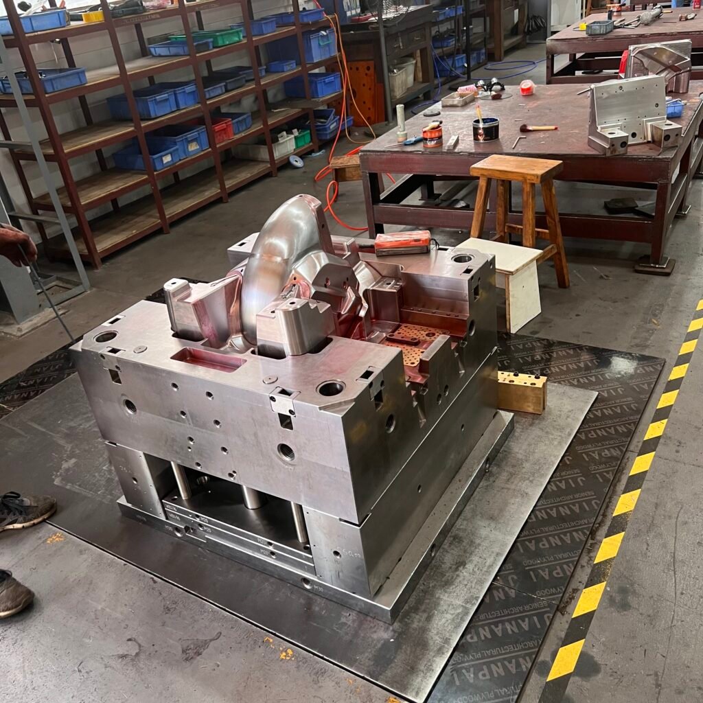
We specialize in high-precision injection molding and mold manufacturing, Import manufacture, and BFY Mold. From a manufacturer with a state-of-the-art facility with skilled professionals to provide you with the best solutions for your manufacturing needs. Our services include:
- Injection Molding and Mold Manufacturing: Industry-leading custom solutions.
- We offer Mass Production & On-Demand Production.
- CNC Processing and Mirror Spark: Sourced from the top CNC machining manufacturers.
- High-Level Mold Tooling Services: From concept to design and prototype to volume, we get the best results.
BFY Mold provides the knowledge and resources needed to assist with your project, whether you require anything from prototypes to low-volume production to large-scale production.
