Whether you are designing precision mold components, assembling CNC machined metal parts, or engineering interlocking plastic enclosures, understanding mechanical fits is absolutely critical. If a fit is too tight, the assembly might crack; if it’s too loose, the mechanism will rattle or fail to function.
In mechanical engineering, mating parts generally fall into two primary categories: Press Fits and Slip Fits.
In this comprehensive guide, we will explain the differences between a press fit and a slip fit, explore their specific engineering applications, and provide crucial design tips for applying these concepts to plastic injection molded parts.
What is a Press Fit (Interference Fit)?
A press fit, also known technically as an interference fit or friction fit, occurs when the internal component (like a shaft or a pin) is intentionally designed to be slightly larger than the external component (the hole or the bore).
Because the shaft is larger than the hole, the parts cannot be assembled by hand. They must be forced together using a hydraulic press, an arbor press, or thermal expansion techniques (heating the outer part or freezing the inner part). Once assembled, the resulting friction creates a very strong, semi-permanent or permanent bond without the need for screws, adhesives, or welding.
Common Applications for Press Fits
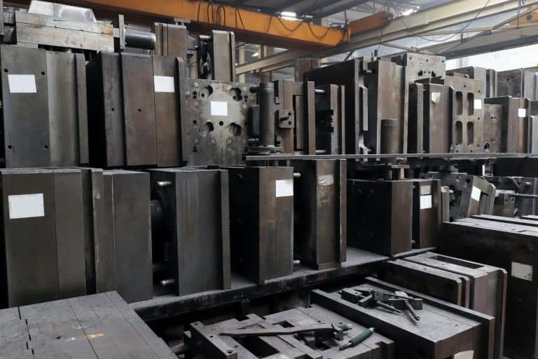
- Mold Tooling: Inserting dowel pins into mold bases to ensure perfect alignment between the cavity and core halves.
- Mechanical Assemblies: Pressing metal ball bearings into plastic or metal housings.
- Gears and Motor Shafts: Securing a gear tightly onto a rotating motor shaft so they spin as a single unit.
What is a Slip Fit (Clearance Fit)?
A slip fit, formally known as a clearance fit, is the exact opposite. In this scenario, the internal component (shaft) is designed to be slightly smaller than the external component (hole).
This intentional gap, or clearance, allows the two parts to slide together easily by hand. Depending on the tolerance designed by the engineer, a slip fit can range from a very precise “locational fit” (where the parts slide together snugly with almost no wobble) to a “running fit” (which leaves enough room for thermal expansion and lubrication).
Common Applications for Slip Fits
- Moving Mechanisms: Shafts that need to rotate freely within a bushing or bearing.
- Mold Components: Ejector pins moving smoothly through the ejector plate of an injection mold.
- Consumer Products: Removable battery covers, interlocking plastic caps, or sliding tracks.
Press Fit vs. Slip Fit: Key Differences Compared

To help you choose the right fit for your mechanical design, here is a quick technical comparison:
B2B Engineering Data Comparison:
| Feature | Press Fit (Interference Fit) | Slip Fit (Clearance Fit) |
| Size Relationship | Shaft > Hole | Shaft < Hole |
| Assembly Method | Requires mechanical force (press) or thermal assembly. | Assembled easily by hand. |
| Friction / Movement | Extremely high friction; no relative movement allowed. | Low friction; parts can slide or rotate freely. |
| Permanence | Permanent or semi-permanent. | Easily disassembled and reassembled. |
| Tolerance Requirement | Requires highly precise machining (tight tolerances). | Can accommodate looser tolerances (unless it’s a precision running fit). |

Designing for Press Fits in Plastic Injection Molding
While press fits are standard in metalworking, applying them to plastic injection molded parts requires a different engineering approach. Metal is rigid, but plastic is viscoelastic—it bends, yields, and creeps over time.
If you are designing a plastic housing that requires a metal pin or bearing to be press-fit into it, keep these DFM (Design for Manufacturing) guidelines in mind:
1. Watch Out for Hoop Stress
When you force a metal pin into a plastic hole (boss), it creates radial tension known as hoop stress. If the interference is too high or the plastic wall is too thin, the plastic boss will crack immediately or fail days later due to stress relaxation.
- Rule of Thumb: Ensure the outer diameter of the plastic boss is at least 2 times the diameter of the inserted metal pin to withstand the expansion forces.
2. Add a Lead-In Chamfer
Never design a sharp 90-degree edge for a press fit. Always include a chamfer (a slight bevel) at the entrance of the plastic hole. This acts as a guide for the metal pin, centering it during assembly and preventing the pin from shaving off plastic material as it is pushed in.
3. Consider Insert Molding as an Alternative
If your design requires a metal thread or pin to be permanently fixed in a plastic part, a press fit might not be the most reliable option due to plastic creep. Instead, consider Insert Molding, where the metal component is placed directly into the mold cavity, and the plastic is injected around it. This creates a superior, indestructible bond.
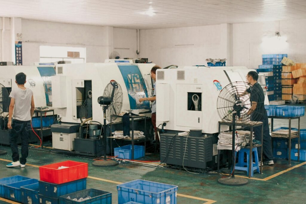
How BFY Mold Achieves Precision Fits
Whether it is machining the hardened steel components of an injection mold or manufacturing thousands of interlocking plastic parts, precision is everything.
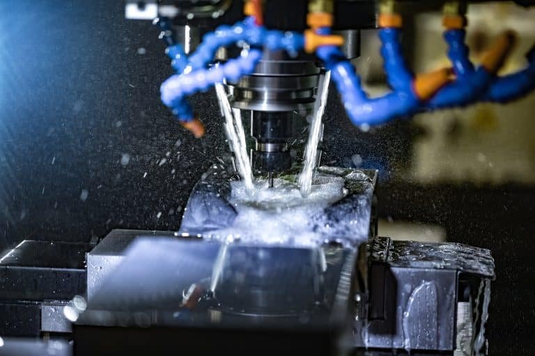
At BFY Mold, we utilize state-of-the-art 5-axis CNC machining centers and EDM (Electrical Discharge Machining) equipment. Our experienced toolmakers can achieve machining tolerances down to ±0.005mm on steel tooling, ensuring that every dowel pin press-fits flawlessly and every ejector pin slip-fits with perfect clearance.
For your plastic parts, our engineers run advanced Moldflow analyses to predict plastic shrinkage, ensuring that the molded dimensions perfectly match your CAD drawings for seamless end-user assembly.

Frequently Asked Questions (FAQ)
Q1: What is a Transition Fit?
A transition fit is the middle ground between a slip fit and a press fit. Depending on the exact machining tolerances of the specific batch, the assembly might result in a very tight clearance fit or a very light interference fit. It is typically used for precise locational alignment where minimal force is required for assembly.
Q2: How much interference is needed for a plastic press fit?
It depends heavily on the type of plastic. For stiff, brittle plastics like Polycarbonate (PC) or Acrylic, the interference should be minimal (e.g., 0.02mm to 0.05mm). For softer, more ductile plastics like ABS or Nylon, the interference can be slightly higher (e.g., 0.05mm to 0.10mm).
Q3: Can a slip fit be waterproof?
No, a standard mechanical slip fit will not be waterproof on its own because there is a physical gap between the parts. To achieve a waterproof seal, you must incorporate an O-ring, a rubber gasket, or utilize a secondary process like ultrasonic welding or overmolding (2K molding).
Need High-Precision Manufacturing?
If your next project requires complex mechanical assemblies, tight-tolerance tooling, or precision plastic injection molding, our engineering team is ready to assist.
[Contact BFY Mold Today] to discuss your project tolerances and get a free DFM review and quote.