Achieving High-Precision Injection Molding Tolerances (±0.05mm)
When a mechanical engineer transitions from designing CNC machined metal parts to designing plastic injection molded parts, they often encounter a harsh reality: Plastic moves. Unlike a block of aluminum that remains dimensionally stable after machining, molten plastic shrinks, warps, and relaxes as it cools. If a product designer slaps a blanket ±0.01mm tolerance across a 150mm plastic housing, they are asking for the physically impossible. However, when interlocking gears, waterproof enclosures, or medical devices demand absolute precision, achieving tight injection molding tolerances is non-negotiable.
In this advanced engineering guide, we will break down the realities of plastic shrinkage, compare the tolerance capabilities of various resins, and reveal how master toolmakers achieve high-precision tolerances down to ±0.05mm.
Standard vs. High-Precision Tolerances
In the plastic manufacturing industry, tolerances are generally classified into two categories:
- Standard Commercial Tolerances (±0.10mm to ±0.20mm): This is acceptable for the vast majority of consumer goods, external housings, and non-moving parts. It is cost-effective and can be achieved with standard P20 steel tooling and typical processing parameters.
- High-Precision Tolerances (±0.05mm or tighter): This is required for complex mechanical assemblies, gears, press fits, and optical components. Achieving this level of accuracy requires hardened steel molds, precision CNC machining, and highly regulated “scientific molding” processes.
The 3 Pillars of Precision Injection Molding
To hit a ±0.05mm target consistently over a production run of 100,000 parts, three interconnected variables must be perfectly controlled:
1. The Material (Shrinkage Rate)
Every plastic resin shrinks as it cools from a molten liquid to a solid. The higher the shrinkage rate, the harder it is to control the final dimensions.
- Amorphous Plastics (e.g., PC, ABS): These plastics have a random molecular structure. They shrink less and very uniformly, making them the best candidates for tight-tolerance parts.
- Semi-Crystalline Plastics (e.g., Nylon, POM/Delrin): These plastics form highly ordered crystalline structures as they cool, leading to significantly higher and often asymmetrical shrinkage (warpage).
B2B Engineering Data: Resin Shrinkage & Attainable Tolerances
| Plastic Resin | Typical Shrinkage Rate | Attainable High-Precision Tolerance | Machining / DFM Notes |
| Polycarbonate (PC) | 0.5% – 0.7% | ±0.03mm – ±0.05mm | Excellent dimensional stability; ideal for tight tolerances. |
| ABS | 0.4% – 0.8% | ±0.05mm | Very predictable shrinkage. (See our [ABS Molding Guide]). |
| POM (Delrin) | 1.5% – 2.0% | ±0.08mm – ±0.10mm | High shrinkage makes tight tolerances challenging. |
| Nylon 66 (PA66) | 1.0% – 1.5% | ±0.08mm – ±0.12mm | Absorbs moisture after molding, causing dimensions to swell slightly over time. |
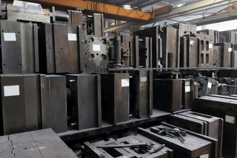
2. The Mold Tooling Precision
You cannot mold a ±0.05mm plastic part from a mold that was machined with a ±0.10mm error. The steel mold dictates the ultimate baseline of precision.
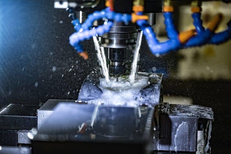
To achieve high-precision plastic parts, the mold cavity and core must be CNC machined and EDM (Electrical Discharge Machined) to tolerances of ±0.005mm to ±0.01mm. This requires rigid, hardened tool steel (such as H13 or S136) because softer aluminum or P20 steel will deflect under high injection pressures, throwing the dimensions out of spec.
3. Thermodynamic Process Control
Once the mold is perfect and the material is selected, the injection molding machine takes over. If the mold temperature fluctuates by 5°C, or the injection holding pressure drops slightly, the volumetric shrinkage of the plastic changes, and the part falls out of tolerance. Precision molding requires closed-loop, sensor-driven injection machines that monitor cavity pressure and temperature in real-time.

DFM: How to Design for Tight Tolerances
As a product designer, your CAD model directly impacts whether the manufacturer can achieve your required tolerances. Follow these Design for Manufacturing (DFM) rules:
- Maintain Uniform Wall Thickness: Thick walls cool slower and shrink more than thin walls. If a part has uneven walls, it will warp, completely destroying your dimensional tolerances.
- Avoid Tight Tolerances Across the Parting Line: The “parting line” is where the two halves of the steel mold meet. Because the mold must open and close, microscopic variations (flash or mold “breathing”) can occur here. Whenever possible, design critical dimensions (like the diameter of a shaft hole) to be formed entirely within a single half of the mold.
- Specify “Critical-to-Function” (CTF) Dimensions: Do not apply a ±0.05mm tolerance to the entire part. Identify the 2 or 3 specific dimensions that are critical for assembly (like a press-fit boss or a gear pitch), and allow looser tolerances for cosmetic or non-functional areas. This drastically reduces your tooling costs and cycle times.
How BFY Mold Achieves ±0.05mm
At BFY Mold, we specialize in engineering projects where failure is not an option. We routinely manufacture high-precision enclosures, automotive sensors, and mechanical gears that demand absolute dimensional integrity.
- In-House High-Speed CNC: We don’t outsource our tooling. Our in-house 5-axis CNC machining centers and wire EDM machines cut hardened steel to tolerances of ±0.005mm.
- Moldflow Simulation: Before cutting steel, we run advanced software simulations to predict exactly how the plastic will shrink and warp, allowing us to build “steel-safe” tolerances into the mold design.
- Rigorous Quality Control: We utilize automated CMM inspection, Go/No-Go gauges, and strict First Article Inspection (FAI) reports to guarantee every batch matches your CAD data perfectly.
Frequently Asked Questions (FAQ)
Q1: What is DIN 16901 / DIN 16742?
These are internationally recognized German standards that define acceptable tolerance grades for plastic molded parts. They provide realistic tolerance charts based on the part’s nominal dimensions (size) and the specific plastic resin used, helping engineers set achievable expectations.
Q2: Will post-molding processes affect my tolerances?
Yes. If your part absorbs moisture (like Nylon) or is exposed to high ambient heat after molding, its dimensions will change. Additionally, processes like ultrasonic welding or high-temperature baking for paint can release internal molded-in stresses, causing slight dimensional shifts.
Q3: Can I get a ±0.01mm tolerance on a plastic part?
For extremely small, specialized micro-molding applications (like tiny medical gears), ±0.01mm is possible using LCP (Liquid Crystal Polymer) or specialized engineering resins. However, for standard macro-sized parts, ±0.01mm is generally not physically sustainable due to daily temperature and humidity variations affecting the plastic.
Don’t Let Poor Tolerances Ruin Your Assembly
If your current supplier is struggling to maintain dimensional consistency, it’s time to upgrade your manufacturing partner.
[Get a Free DFM Review Today] – Upload your CAD models and 2D drawings with your Critical-to-Function (CTF) tolerances. Our engineering team will analyze your design and provide a high-precision tooling quote within 24 hours.